Graphical User Interface (GUI) Windows Program
The demo code is provided in source code form to help the user to understand the operation of the ArduCAM USB camera and SDK library.
Before you start, make sure:
- You have downloaded the latest device driver, SDK library and examples can be downloaded from
https://github.com/ArduCAM/ArduCAM_USB_Camera_Shield - You have installed the drivers needed as instructed in the Windows Driver Installation chapter.
1. Run the Program
The Windows demo code is located in ../Winodws/GUI/USBTest folder and the release executable software is located in ../Winodws/GUI/USBTest/x64/Release/USBTest.exe.
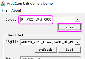
2. Scan Cameras
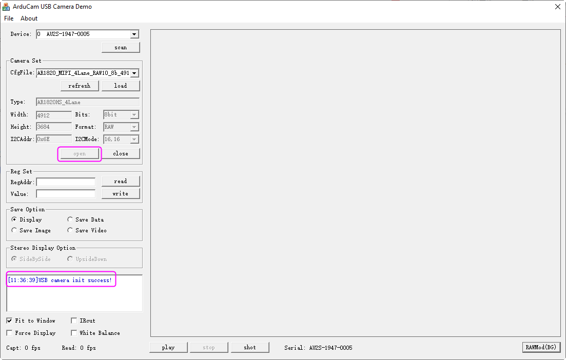
Click the 【**scan**】 button, the drop-down list will show all supported cameras with a serial number, user can select one of them to open.
3. Load the Camera Settings
There are several preset of the camera settings in the ../Config folder,
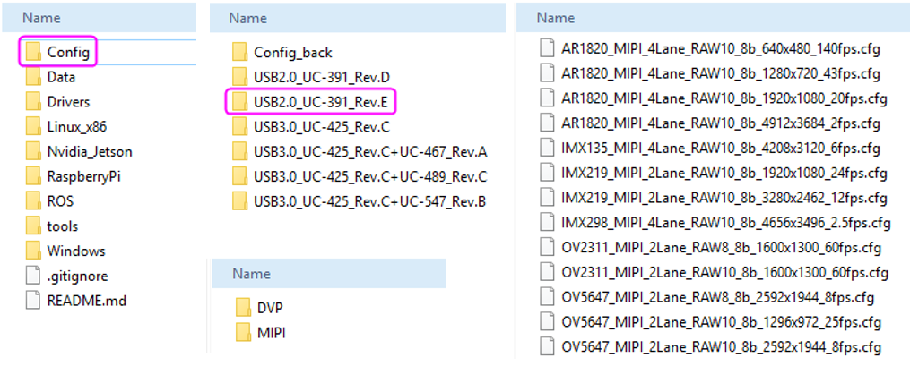
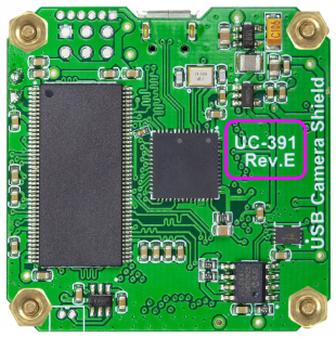
- Confirm the board number of the circuit board,
- Click the
【**File**】–【**Open**】button, select the config folder, then select the folder corresponding to the board number and interface, and select the required camera configuration file, - Click
【**load**】to load the setting. The camera type, width, height, bits, format, I2CAddr, I2CMode will be loaded with the correct values.
4. Open the Camera
Click 【**Open**】 to initialize the camera. There will be a prompt in the text area after initialization.
5. View Hardware Version Number
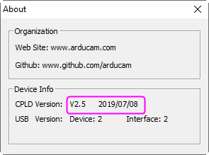
After opening the camera, you can click the 【About】 button to view the hardware version number.
Tips
Before viewing the hardware version number, be sure to click Open, Otherwise, the version number cannot be displayed.
6. Play the Video
Click the 【**Play**】 to capture and display the video in real-time.
The lower-left corner will show the number of frames.
7. Stop the Video
Click the 【**Stop**】 button to stop the video capture and display.
8. Take a Snapshot
When playing the video, you can click the 【**Shot**】 to take the BMP image to files. The picture is stored in the ../Windows/GUI/USBTest/x64/Release/Shot folder.
9. Sensor Register Read/Write
This is very useful to access the sensor register in order to adjust the sensor settings on the fly. For example, you want to manually change the exposure settings you can input the exposure register address and value then click write, you can video how the brightness changes from the video.
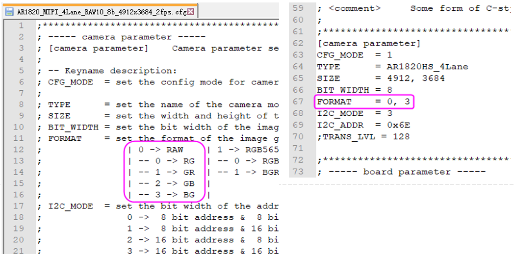
10. RAW Mode Selection
There are four combinations of the RAW format R-G, G-R, B-G, G-B. It is predefined for the tested camera, you can also change the mode match your target sensor RAW display order.
After confirming the raw mode online, you can modify the settings in the configuration file.
11. Camera Control
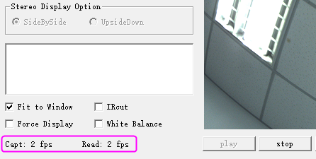
11.1. Fit to Window
To fit the captured image to the GUI windows size. If this is unselected, user can use a mouse scroll wheel to zoom in and out the real-time video, or drag the mouse cursor to move the video position.(【Fit to window】 is selected by default.)
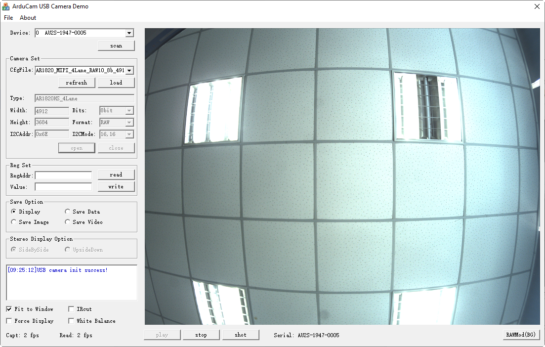
11.2. Force Display
Force display is useful to debug the problem by force displaying the wrong video data which is a mismatch with the camera preset values.
For example, as shown in the figure above, we first modified the configuration file, change the CFG_MODE value to 0, and reload the configuration file. In this way, the Width and Height of the interface are editable. Then change the Height value from 3684 to 3680. After clicking 【play】, because the resolution doesn’t match, the text area will prompt “bad frame received”, and the image cannot be displayed. Then select 【Force Display】, the image will be forced to display.
11.3. IRcut
It can be used to manual control extra motorized IRCUT filters for both daylight and night vision.
11.4. Frame Rate Information
The frame rate information shows the capture frame rate (Capt) and GUI display frame rate (Read). These two values might be mismatched, due to the performance of the demo GUI software and computer hardware.
12. Image Save Options
There are several options for saving image files and formats.
- The
【Display**】**option doesn’t save any file just real-time display the video from the camera.
- The
【Save Data】option is used to save the continuous images in the same format as the camera output like RAW, RGB, YUV or JPEG.
- The
【Save Image】option is used to save the BMP images.
- The
【Save Video】option is used to save the AVI format video.
Except for the 【Display】 option, when checking other options, the video is not updated on the display region. All the saved files are located in the Record folder. The files are stored in the ../Windows/GUI/USBTest/x64/Release/Record folder.